The box beam of uniform thickness (Fig. below) is subject to a moment of 30 kNm. a. Determine the maximum bending stress in the beam. b. Determine the orientation of the neutral axis.
The thin-walled member in Fig. 4 below has a slit along its section. a. Draw the shear flow diagram of the section ( i.e. , arrows only). (10%) b. Determine the location e of the shear centre, O
Your client wants to install a heavy safe on the second floor of a building. As the structural engineer, you decide to reinforce the existing timber bearer by specifying a parallel flange channel (PFC) screw fixed to the bearer in the configuration shown (Fig. 2 overleaf). The beam shear X6 of the composite beam has already been calculated for you. Refer to tables and the appendix for timber bearer sizes and PFC details. NOTE: The modulus of elasticity of spotted gum is approximately 20GPa compared to 200GPa for steel. a. The timber beam consists of multiple laminations of 45mm spotted gum. Determine the longitudinal shear stress t at the interface between the two lowermost laminations of the bearer(.e., 45mm above the bottom of the bearer) if the floor was loaded up before the PFC could be installed? b. You specify to the builder that the PFC must be fixed to the timber beam with coach screws at 300mm spacings. Allowing a factor of safety of 2, what is the minimum...
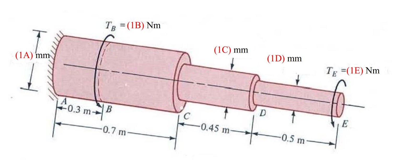
1. The solid steel circular shaft (Fig. 1), known as a stepped shaft, is subjected to torque TB and TE as shown. The shear modulus for steel is G = 80 GPa. a. Draw the torque diagram for the shaft. b. Determine the shear stress at the shaft surface in section AB, BC, CD and DE. c. Determine the angle of twist at E
An I-beam below is loaded with a point load in the middle. Given the crosssection shown, determine the shearing stresses at the levels 1-1, 2-2, 3-3 & 4-4 .
The solid circular shaft below is sometimes referred to as a stepped shaft. Compute the shear stress and angle of twit caused by the application of the various torques at two locations. Plot torque, shear stress and rotation diagrams. Take G = 80 GPa.
For the truss below, determine the vertical displacement at Joint E. Take E as 200 GPa, member area A (500 mm 2 ) except member AC is taken as 1.5*A (750 mm 2 )
In the sway frame below, using Moment Distribution Method, determine the bending moments and the shear forces from equilibrium. Then plot the shear force and bending moment diagrams. The E and I values for each member are given.
In the non-sway frame below, using Moment Distribution Method, determine the bending moments and the shear forces from equilibrium. Then plot the shear force and bending moment diagrams. The E and I values for each member are given.